
Introduction
Fluid statics deals with fluids at rest and a central result is Archimedes’ Principle any object that is completely or partially submerged in a fluid experience an upward force, called the buoyant force, equal to the weight of the fluid that the object displaces. This one principal accounts for why ships float, why a submarine can dive and rise as it wants, why a swimmer feels lighter in water than air. To make this theory a practical engineering exercise our team designed, built and tested a scaled down submersible system essentially a miniature, battery powered submarine from inexpensive, readily available materials. Building a functional submersible forces a designer to confront the same trade-offs that confront real underwater vehicle engineers: the hull must displace enough water to generate adequate buoyant force; the total mass of the structure, electronics, and ballast must be carefully balanced with that buoyant force to achieve neutral buoyancy the object doesn’t sink or rise uncontrollably and the propulsion system must run from inside a fully sealed, watertight compartment.
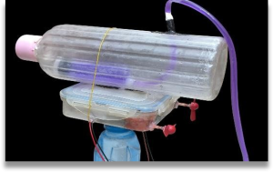
Figure 1. The assembled submersible system: cylindrical bottle hull joined to the rectangular electronics enclosure.
Methodology
System Design Concept
The submersible hull is divided into two parts, mechanically bonded and then sealed together to make one watertight hull (Figure 1):
- A cylindrical bottle chamber (a repurposed PET beverage bottle) is the core pressure-tight chamber in the system, which contains the majority of the system’s buoyant displacement.
- A rectangular electronics enclosure a small plastic box to which the two internal 180 DC drive motors and the dead weight ballast (to lower the center of gravity below the center of buoyancy) are installed. No batteries or driver electronics are exposed to water pressure inside the hull; the battery pack and the manual speed-control potentiometers are in a separate, external control box, which is tethered to the motors.
The two parts are clamped together with tensioned steel wire ties for mechanical rigidity, and every seam, cable entry and tube fitting is sealed with hot-melt adhesive to prevent water ingress.
Propulsion: Twin-Motor Differential-Thrust Drive
Each one is an 180-type DC motor, mounted side-by-side (left and right) and each one with its own external propeller directly on a short shaft through the side of the dead-load box. The shaft penetration is not eliminated by using a magnetic coupling, but rather each point is merely filled with waterproof adhesive when assembled .This twin-motor setup is the reason that a steering by differential thrust can be accomplished, instead of using a rudder: If both propellers turn at the same speed, the vehicle is driven straight forward; If one motor is made faster and the other slower, or stopped, the nose is turned toward the slower motor. Fixed dead weight ballast is also situated in the lower box, that is attached to reduce the center of gravity below the center of buoyancy to prevent the vehicle rolling over in the water.
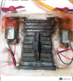
Figure 2. Interior of the lower drive/dead-load box, showing the stacked metal dead-weight ballast (center) flanked by the two internal 180 DC drive motors. The propeller shafts and their sealed box penetrations are visible at the top edge of the enclosure.
Cyclone multipurpose grease was applied at each motor shaft and its box-wall penetration point to reduce friction and provide an additional moisture barrier at this sealed, moving joint.
Buoyancy / Ballast Control Mechanism
A syringe is connected via flexible tubing through a sealed port into the bottle chamber. By manually pushing the plunger in or drawing it out, the operator can inject or withdraw a small, controlled volume of water from the chamber. This is a simplified analogue of the ballast tanks used on full scale submarines adding water increases the system’s weight without changing its displaced volume, reducing net buoyancy and allowing the vehicle to descend, while withdrawing water has the opposite effect.
Electrical Power and Motor Control
The two DC Drive Motors are rated to 12 V. They are connected in series (not in parallel) to get the voltage of the cells as well: 12 V = 3.7 V × 3. The result is a rail dropping to 11.1 V, which is near, but still below, the motor limit of 12 V, for nearly full torque and speed with a little margin for safety. The battery pack and all the speed control are in an external, tethered control box, completely out of the water. The 11.1 V rail splits into two lines, one serving a manual rotary potentiometer which controls the speed of the first motor, and a second serving a similar potentiometer which controls the speed of the second motor. The two potentiometers can be adjusted independently by hand, so that the speed of the motors on each side can be controlled independently in real time, and this is the basis for controlling the steering by differential thrust as described in Section 2.2. Power from the control box is transmitted to the two motors inside the lower sealed drive box through long, red and black/white tether wires..
Theoretical Basis for the Buoyancy Calculations
Three governing relationships were used to size the buoyancy and ballast of the system:
- Volume of a rectangular solid: Vb=L×W×H
- Volume of a cylinder:
Vcyl=(π/4)d2h
where L, W, H are the length, width and height of a rectangular part, and d, h are the diameter and height of a cylindrical part.
- Archimedes’ Principle, giving the buoyant force on a fully submerged body:
Fb=ρ×Vsystem×g
where ρ is the density of water (1000 kg/m3), Vsystem is the total volume the assembled hull displaces, and g is gravitational acceleration (9.8 m/s2).
- Static equilibrium condition used to find the ballast mass x required for neutral buoyancy, where the total downward weight force must equal the upward buoyant force:
g×(Mcurrent+x)=Fb
where Mcurrent is the fixed mass of the assembled system before any additional ballast is added.
Assembly and Waterproofing
- Measure, cut and clean the bottle and the electronics box to the necessary size.
- Make or drill a hole on the side of the bottle chamber for the internal ballast syringe; affix the two 180 DC drive motors side by side in the lower drive/dead-load box.
- The flexible orange tubing is used to connect one end of the flexible tubing to the internal syringe nozzle and the other end to the external control syringe to create the closed hydraulic ballast line.
- In the outside control box, wire the three lithium ion cells in series for a 11.1 V output, and take the 11.1 V rail to a separate rotary potentiometer for each motor, to independently adjust the speed of each motor.
- Protect against friction and aid sealing of this moving joint by applying Cyclone multipurpose grease to each motor shaft and its box-wall penetration point and add dead-weight ballast in the lower box to lower the center of gravity below the center of buoyancy.
- Use a hot-melt glue gun to bond the bottle–box joint and ballast-tube entry together to create a watertight seal.
- Use tensioned steel wire ties to attach the bottle to the box for mechanical strength.
- Solder the tether wires to motor ends, run them out through sealed lower box exit points and solder to external control box, mount propellers directly on motor shafts.
Results
Geometric Volume Analysis
The total displaced volume of the hull was measured from its two sections using the formulas in Section 2.5:
| Component | Formula | Dimensions | Volume |
| Rectangular box | L×W×H | 14 × 14 × 4 cm | 784 cm³ |
| Bottle (main body) | (π/4)d2h | d = 10.0, h = 26.0 cm | 2042.04 cm³ |
| Bottle (neck) | (π/4)d2h | d = 4.0, h = 2.5 cm | 31.42 cm³ |
| Bottle (cap assembly) | Empirical constant | 0.01 cm³ | |
| Total bottle chamber | Σ segments | 2073.46 cm³ | |
| Total system volume | Vbox+Vbottle | 2857.43 cm³ |
Vsystem= 2857.43 = 2.85743 × 10⁻³ m³
Buoyant Force (Archimedes’ Principle)
Fb=ρ×Vsystem×g=1000kg/m3×(2.857×10−3m3)×9.8m/s2=28.003N
This is the maximum upward force that the surrounding water exerts on the hull when it is fully submerged.
Mass Inventory and Ballast for Neutral Buoyancy
| Fixed mass component | Mass |
| Fluid-filled main bottle enclosure | 1923 g |
| Structural outer housing box | 152 g |
| DC propulsion motors & framework | 12 g |
| Total fixed mass, M_current | 2087 g (2.087 kg) |
Solving the static-equilibrium condition from Section 2.5 for the required ballast mass x:
x=Fb/g−Mcurrent
= (28.003 N / 9.8 m/s²) − 2.087 kg = 2.85743 kg − 2.087 kg ≈ 0.77043 kg (770.43 g)
Electrical Configuration Check
Three 3.7 V cells in series provide a total of 11.1 V, which results in a margin of safety of approximately 7.5% below the maximum motor rating of 12 V, but still provides close to maximum torque and speed. This single rail of 11.1 V is used for the 2 motor-driver boards and both boards get the same voltage from this rail, allowing both motors to be controlled independently.
The 2087g fixed mass consists of the bottle enclosure, that is filled intentionally with water as a base trim weight, and the fine (but not bulk) ballasting is made by adjusting the depth and trim with the syringe-and-tube mechanism described in Section 2.3. A second important lesson for a fluid mechanics course from the sensitivity shown in Table 3.3 is that a single dimension that is incorrectly measured or typed in a hand calculation can lead to a large error in the final ballast required. Even in a full-scale submarine or ROV, this accuracy is significant enough to make the difference between one that reaches its design specifications for neutral buoyancy and one that will not sink at all hence, the need for multiple independent measurements of the displacement before any ballast is added. A full hydrostatic stability check (finding the centre of buoyancy and centre of gravity to ensure that the vehicle will NOT capsize) was not looked at in this project, but would be a logical extension, and would combine calibrating the relationship between syringe-ballast volume and resulting dive depth to get repeatable depth control.
This project has been successfully designed and fabricated the low cost miniature submersible system which in a tangible way demonstrates the fundamental principles of fluid mechanics such as hydrostatics and buoyancy. Once an arithmetic error in the volume of the box is corrected, the assembled hull has a volume of approximately 2857 cm³ and a buoyancy of about 28.003 N, but a fixed system mass of 2.087 kg, so requires about 0.77 kg of extra dead-weight ballast to bring to neutral buoyancy.
The project also tested a twin direct-drive propulsion system in which two independently-controlled 180 DC motors drive external propellers directly from sealed shaft penetrations in the lower drive box, offering the vehicle working differential-thrust steering from a completely external, tethered control u
Range of resources : involves the use of diverse resources (people, money, equipment, materials, information and technologies).
| Resources | Report Components |
| Materials | PET beverage bottle (hull), plastic storage box (drive/dead-load box), orange vinyl tubing, hot-melt adhesive, steel wire ties |
| Equipment, Tools | Syringes (ballast actuator pair), soldering iron, basic hand tools, drill |
| Technologies | 180 DC drive motors, rotary potentiometer speed controllers, 3.7 V lithium-ion cells |
| Equipment, People | Water-immersion test basin; project team members |