
Introduction
Fluid mechanics is a basic engineering discipline that is concerned with the study of fluids in motion and at rest. Knowing how air flows around objects is critical in the design and analysis of aircraft, cars, wind turbines, buildings, bridges, and many other engineering systems. A wind tunnel is one of the best experimental tools available for the study of the aerodynamic characteristics when air is made to flow over a stationary test model. By using a wind tunnel, wind tunnel engineers can visualize airflow patterns, investigate flow separation, wake formation, turbulence, and aerodynamic forces such as drag and lift. These experiments offer useful information about the performance, efficiency and stability of engineering design without requiring a full-scale test, thus saving considerable cost. This project involved designing and building a low-cost subsonic wind tunnel from readily available materials including a honeycomb flow straightener, acrylic sheets, cardboard, and an “axial fan”. The developed system provides a more uniform airflow to a transparent test section for smoke visualization of airflow around various test models. The project is simple, economic and educational, showing the basic aspects of fluid mechanics in a simple but informative way suitable for undergraduate laboratory experiments.
Methodology
Fabrication Procedures
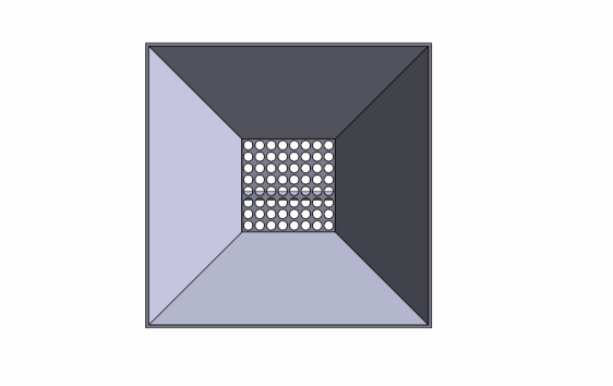 Diffuser
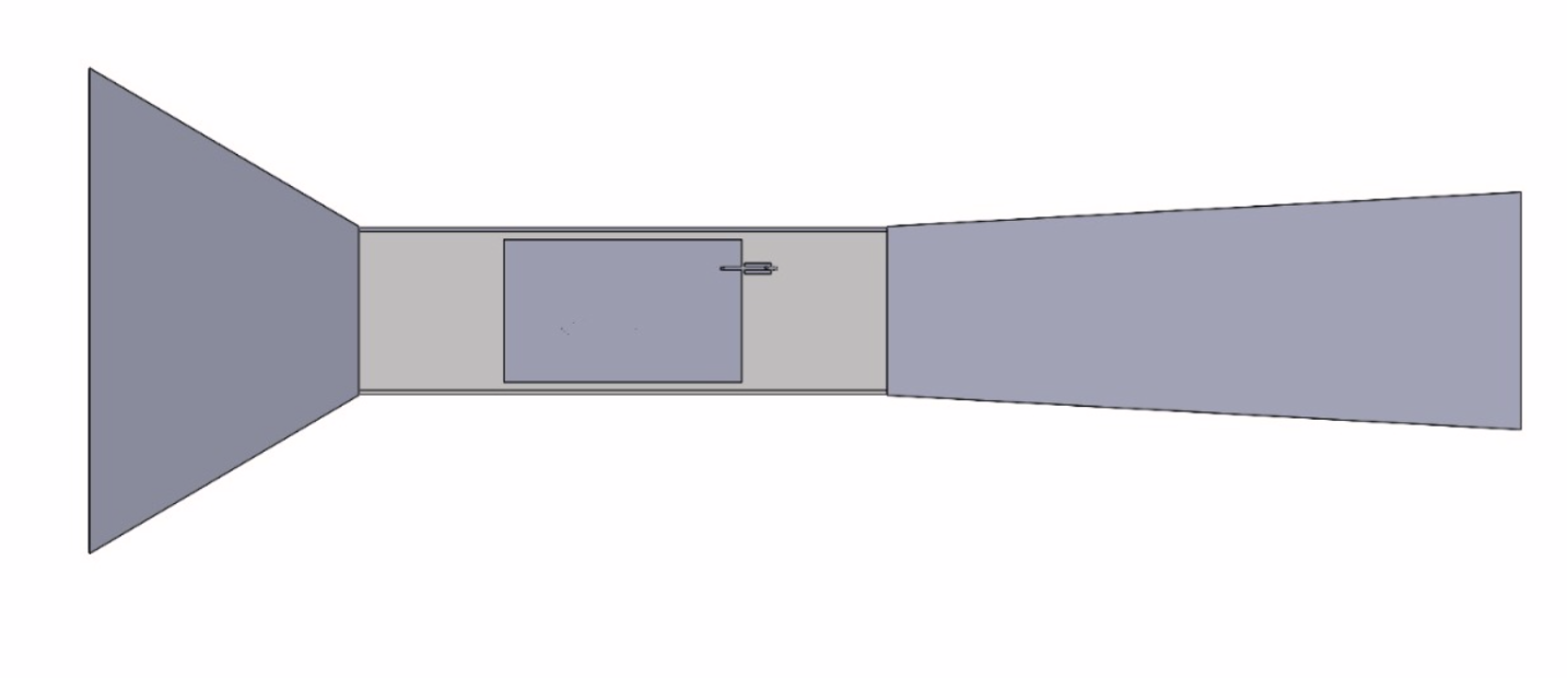
Figure 01: SolidWorks design of Wind tunnel
Contraction Observer Honeycomb
- The outer section, the testing chamber of the wind tunnel, was made from an acrylic sheet to allow clear observation of the airflow. Both the contraction (to gradually reduce the cross-sectional area and increase airflow velocity) and the diffuser, installed to allow gradual expansion and reduce pressure losses, were made of cardboard.
- At the outlet, an axial fan was installed to blow out the air over a bluff body like a bus.
- Plastic straws were used to make a honeycomb and installed at the end section of the contraction section.
- Hot glue was used to make the whole system airtight.
- An e-cigarette was used to make smoke, instead of a smoke generator, to reduce the cost.
CFD Analysis of a bluff body in the wind tunnel
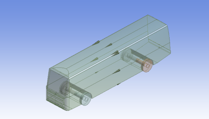
Figure 02: 3D object of Bluff Body
The bluff object, bus, was made by using SolidWorks .
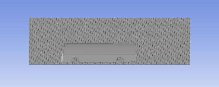
Figure 03: Boolean Subtract Operation
Then object is import to the Design-Modeler to determine the fluid and solid domain.
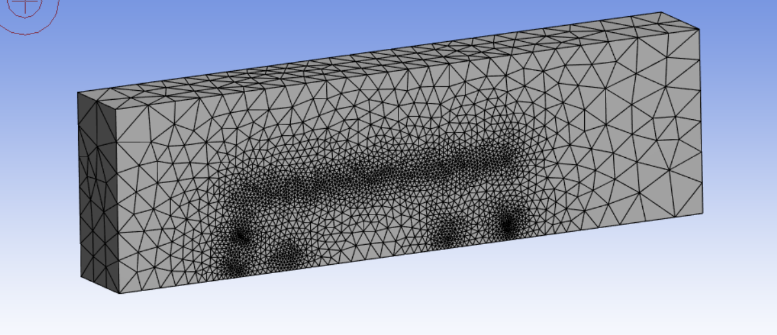
Figure 04: Mesh
Using the default mesh settings mesh is generated. The total note generated is 166420 and total element number is 886151 (Note: Since we are using Ansys student version 2025, we were unable to load more than 1 million elements.)
A CFD simulation was run to visualize the airflow over a bluff body using ANSYS-Parallel Flow. “K-epsilon”, “realizable”, and “Enhanced wall treatment” models were used in this simulation.
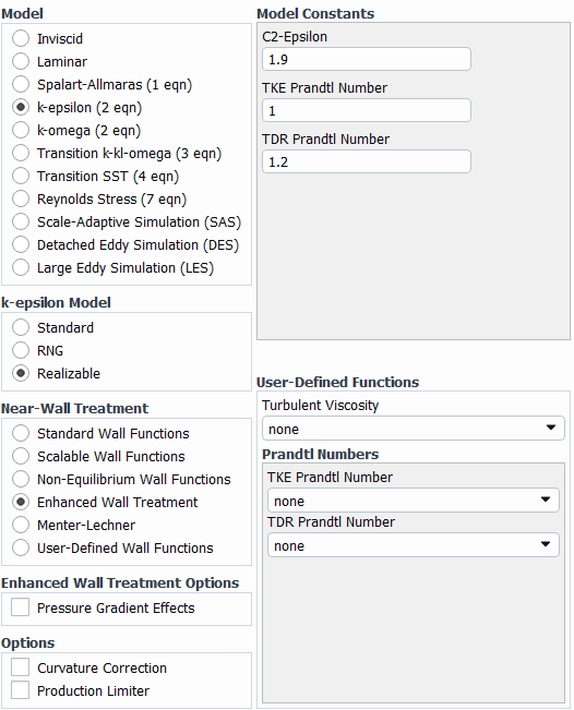
In boundary conditions, in the inlet section, the inlet velocity was taken as 30 m/s

The “Coupled” scheme was selected under “Solution methods”, since it is more robust and faster to converge complex fluid-flow relations like flow over a bluff body, say flow over a bus.

To make the result converge, the calculation was run for 500 iterations

Result
The fabricated subsonic wind tunnel was successfully fabricated, and we successfully generated approximately uniform flow over the bluff body. The “Scaled residual curve” of our simulation converged with a slight fluctuation having the same amplitude, meaning our simulation is correct.

Figure 05: Scaled Residual Curve

Figure 06: Drag coefficient (cd) curve
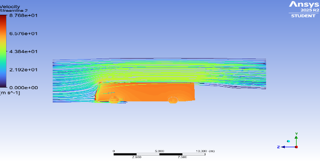
Figure 07: Flow over the bus was indicated by the simulated streamline & real streamline
The Cd curve shows that the curve is not converging to a single point but oscillating periodically, displaying that the flow is physically unsteady.
Conclusion
The fabricated subsonic wind tunnel was successfully used to visualize fundamental aerodynamics with materials and components that were of local origin and affordable. Its use of cardboard, hot glue, and plastic straws, however, restricts its structural integrity, potential for air leaks, and only allows qualitative observations. In the future, the structural parts could be fabricated using 3D printing or PVC and a glycerin fog generator could be included in addition to the Pitot tubes and load cells so that precise quantitative data could be obtained.
Uses diverse resources such as equipment, people, software, materials, money, laboratories, and technologies.
|
Resources |
Project Components |
|
Software, design resources |
SolidWorks, Design Modeler, Ansys |
|
Materials |
PVC board, PVC glass, hot glue, super glue |
|
Equipment |
Fan, measuring scale, Li-po battery |
|
Equipment, People |
Wind tunnel assembly, experimental testing by project team |