
History:
Tesla began experimenting with boundary layer fluid dynamics around 1906. He first publicly showcased a working 200 horsepower model running at 16000 RPM on his 50th birthday July 10, 1906. Tesla filed for his primary turbine patent on October 21, 1909. It was officially granted as U.S. Patent 1061206 on May 6,1913. In a 1912 interview, Tesla unveiled a compact prototype the size of a man’s hat that could generate an impressive 110 horsepower at 9000 RPM. He promoted its simplicity, reversibility and high speed. While it functioned well in controlled settings, the industrial manufacturing standards of the 1913 era could not consistently produce perfectly flat disks at the necessary microscopic tolerances. At extreme high speeds the disks would warp and buckle, causing the engine to fail.
Theory:
Instead of the curved blades found in conventional turbines, Tesla turbine uses a stack of smooth, flat parallel disks mounted on a shaft. Fluid injected at the outer edge spirals inward toward a central outlet and the turbine spins not because fluid strikes blades but because of adhesion and viscosity, the so-called boundary-layer effect. Water or gas passing close to each disk surface drags a thin layer of fluid along with it through friction, and that friction transfers momentum into rotation.
So how this works?
Actually, Fluid injected at the outer edge spirals inward toward a central outlet, and the turbine spins not because fluid strikes blades, but because of adhesion and viscosity the so-called boundary-layer effect. Water or gas passing close to each disk surface drags a thin layer of fluid along with it through friction, and that friction transfers momentum into rotation; as shown at Fig 01.
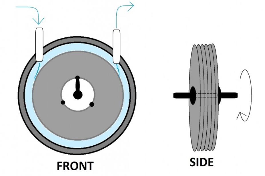
Fig 01. Tesla Turbine’s simplified construction
When unloaded, the fluid between the disks flows at almost the same speed as the disks, resulting in minimum drag. As load is applied and the shaft slows, the fluid retains its angular momentum, resulting in a speed differential between the fluid and the disk surface this differential is what provides useful torque. Tesla observed that the action is partially self-limiting: a pressured fluid band forms at the periphery and automatically restricts additional inflow, making the turbine somewhat self-governing.
Total Construction of a Tesla Turbine:
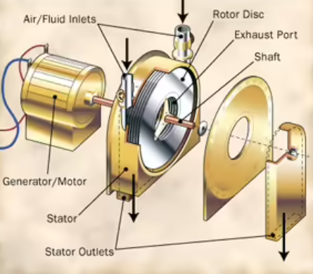
Fig: Construction of Tesla Turbine
- Air/Fluid Inlets: The entry points where the working fluid (air, water, steam, etc.) is injected into the
Turbine housing.
- Rotor Disc: A stack of smooth, closely spaced disks set on a shaft. This is the turbine’s working heart, where fluid drags over the disk surfaces due to viscous friction, rotating the entire stack.
- Exhaust Port: The centre outlet from which the fluid escapes after spiralling inward across the disks and releasing its energy.
- Shaft: The central rod that runs through the disk stack and connects the spinning rotor to whatever it is driving.
- Stator: The rotor disc is surrounded by a motionless outer shell known as the stator. It holds and directs the fluid flow, guiding it from the inlets into the disks and routing it back out through the stator outlets.
- Stator Outlets: Secondary exit outlets on the stationary housing (separate from the central exhaust port) that allow fluid to escape from the stator cavity, assisting in the management of flow and pressure surrounding the rotor without interfering with its spin.
- Generator/Motor: An external unit attached to the shaft that turns the turbine’s mechanical spinning into electrical power (if operating as a turbine) or, when operating in reverse, spins the shaft to drive the disks as a pump.
Application and Advantages of Tesla Turbine:
- According to Tesla’s patents, the apparatus was designed to use fluids as motive agents rather than for fluid propulsion or compression.
- The device can act as both a turbine and a pump by reversing the flow direction.
- Because it lacks blades or striking surfaces, it can handle moist steam, particles, and viscous or multi-phase fluids without causing erosion.
- Because the design scales easily, small portable units can be built for use directly in rivers and streams.
- It can be mounted behind a propeller; it converts the propeller’s accelerated backwash (prop wash) into onboard electrical power during flight.
Limitations:
- Poor nozzle design reduces efficiency: Many performance losses are caused by inefficient nozzle design.
- Nozzles are designed for convenience: Most studies use nozzles that are easy to make rather than optimized for performance.
- Simplified nozzle models in simulations: Simulations often assume ideal nozzle flow, ignoring real-world energy losses.
- Efficient rotor, inefficient nozzle: The rotor works well, but a poor nozzle lowers the turbine’s overall efficiency.
- Needs very high RPM: The Tesla turbine performs efficiently only at very high rotational speeds, which may not be possible to provide all the time, so the overall efficiency declines.
- Better materials increase cost: Stronger materials prevent distortion but make the turbine more expensive, which is contradictory to the low-cost advantage.