
Cavitation is one of the major fluid mechanics problems which damages ship propellers by reducing their efficiency and ultimately affects their performance. It happens when the local water pressure drops too low, falling below the vapor pressure of water. When this happens, the water boils instantly and creates tiny bubbles filled with water vapor. As these bubbles flows along with the flow into areas where pressure is high, they pop very quickly and violently. These small popping bubbles create very strong water jets and shockwaves. After a certain time period, these shockwaves hit the blades repeatedly, chipping away the metal, causing loud noise, making the structure shake, and causing the propeller to lose its pushing power.
5-bladed propellers are used in large ships because the extra blade area of these helps spread out the thrust more evenly compared to 3 or 4-bladed designs. This reduces the heavy workload on each blade. However, these 5-bladed propellers still face severe bubble formation near the blade tips and flat surfaces when spinning fast under heavy loads.
The ultimate goal is to reduce cavitation by adding small grooves on the propeller edge. By adding these tiny grooves, we want to improve the water flow layer and stop bubbles from forming without changing the main propeller shape.
METHODOLOGY
This study tests flow of 2 different surface styles of a 5 bladed marine propeller using 3D printed model. The basic propeller geometry is the typical Wageningen B-series design.
Reference Propeller Selection and 3D Modeling
A 5-bladed marine propeller was first created in the standard 3D geometry in SOLIDWORKS. The dimensions are based on those in the Wageningen B-series propeller data, which give the standard industrial base line data for propeller pitch, chord and skew angles.
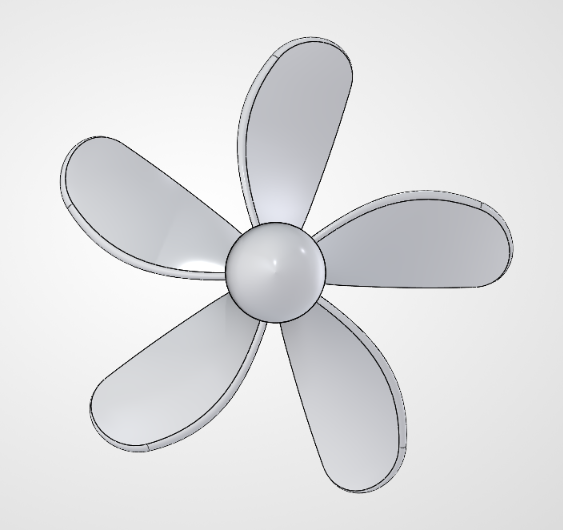 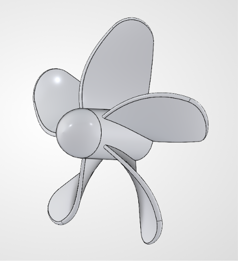 |
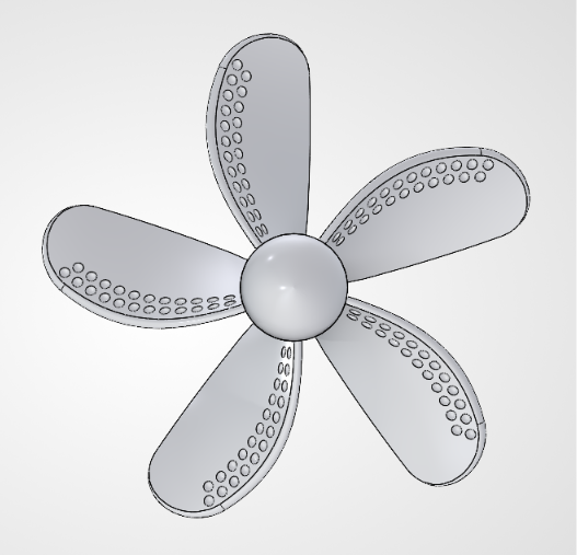 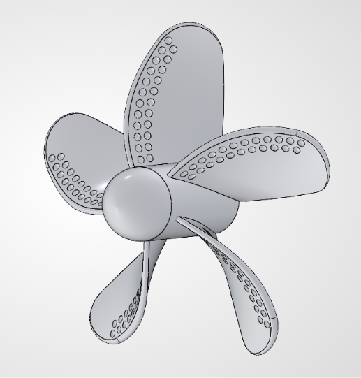 |
| Fig-01: Standard Propeller (CAD Model) | Fig-02: Surface Modified Propeller (CAD Model) |
Surface Modification
Two different 3D propeller models are created for testing the modifications in the surface:
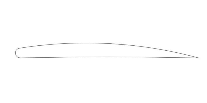
Standard Propeller (Baseline Control): Standard propeller having a complete smooth finish on all five blades.
Surface Modified Propeller (Micro-Textured Surface): Modified by making small spherical grooves on the blade surfaces. These micro-textures go on the edge of the low-pressure suction side of the blade.
 |
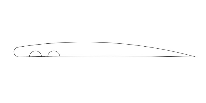 |
| Fig-03: Standard Blade Profile | Fig-04: Modified Blade Profile |
3D Printing Both Propeller Models
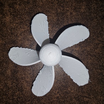
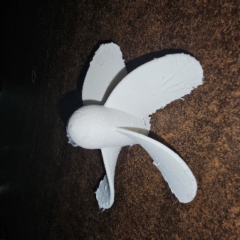
The propellers are made from a PLA filament with an FDM (Fused Deposition Modeling) 3D printer for both designs. The same printing parameters are used for both models so that any differences seen in the tests are due to the modification of the surface and not to manufacturing differences.
  |
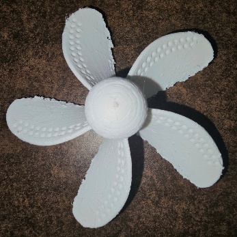 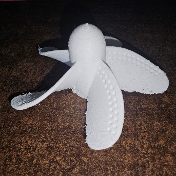 |
| Fig-05: Standard Propeller (3D Printed Model) | Fig-06: Surface Modified Propeller (3D Printed Model) |
Results
The Standard Propeller showed cavitation formation, which can damage the propeller and reduce its lifespan. The Surface Modified Propeller showed a reduction in the cavitation formation. The small surface grooves generated small vortices within the boundary layer, preventing vapor bubbles from merging into large cavities and maintaining relatively higher local pressure near the leading edge.
This study shows that surface modification of a 5-bladed propeller can reduce cavitation. The results indicate that micro-scale surface textures help minimize cavitation without changing the overall shape of the propeller.
Uses diverse resources such as equipment, people, software, materials, money, laboratories, and technologies.
| Resources | Report Components |
| Designing Software | SolidWorks |
| 3D Printing Technologies | FDM (Creality Ender-3 V2) |
| 3D Printing Materials | PLA |
| Equipment | Clear Water Tank, 12V DC Motor, Power Supply |
| Measuring Equipment | Smartphone Camera for Visual Observation |