
Introduction
Every aircraft, drone, and race car owes part of its performance to hours spent not in the sky or on the road, but inside a wind tunnel. In simple terms, a wind tunnel is a controlled channel of moving air — a setup built to recreate, on the ground and at a manageable scale, the same airflow conditions a real object would face in motion. A fan pushes air at a known, steady speed over a stationary model, letting engineers study forces, pressure changes, and flow patterns long before any real vehicle leaves the workshop.
This project grew out of a simple wish: to actually see aerodynamics instead of just calculating it. Lift, drag, and flow separation usually show up as equations on a whiteboard, but a wind tunnel makes them visible — smoke drifting smoothly around a wing at a shallow angle, then breaking into turbulent eddies once the angle gets too steep. Our goal was to build a small, low-cost wind tunnel that could produce steady, visualizable airflow, and then use it to observe how a test aerofoil behaves aerodynamically, using smoke we generated manually.
The tunnel works on Bernoulli’s principle: pressure and velocity in a moving fluid are inversely related, so wherever the tunnel narrows, the air speeds up and its pressure drops — much like the throat of a Venturi tube. The same principle applies along the aerofoil itself: air travels faster over the upper surface, which lowers the pressure there relative to the underside, and that pressure difference is what generates lift. This report walks through how we turned that theory into a working setup, what we saw once we switched it on, and what the whole process taught us as a team.
Methodology
The wind tunnel is an open-circuit design — air gets pulled in from the room, flows through the tunnel just once, and is then pushed back out into the room rather than being recirculated. I built it section by section using foam board and cardboard, mainly because they’re lightweight, easy to cut precisely, and cheap enough that I could mess up and redo a section a few times before locking in the final build. I checked every joint with a spirit level and squared it against a flat table edge as I went, since even a slight tilt or twist in the duct would push the airflow toward one wall of the test section and throw off the smoke pattern.
The final setup, shown below, follows the standard five-stage layout you’d see in any low-speed wind tunnel:
- Inlet section — a bell-shaped mouth that lets air enter smoothly, so you don’t get sharp-edge disturbances seeding extra turbulence right at the start.
- Honeycomb and screen section — a grid of small parallel cells followed by fine mesh screens, which break up the larger swirling eddies and straighten the air into parallel streamlines.
- Contraction section — a tapering duct that narrows the cross-section, which by continuity forces the air to speed up into a faster, noticeably steadier stream before it hits the model.
- Test section — a clear chamber where the 3D-printed aerofoil model sits, with smoke introduced so I could visually trace how the air moved over its surface.
- Diffuser and fan — past the test section, the duct widens out again, slowing the flow down and recovering some pressure, before it finally passes through the electric fan and exits back into the room.
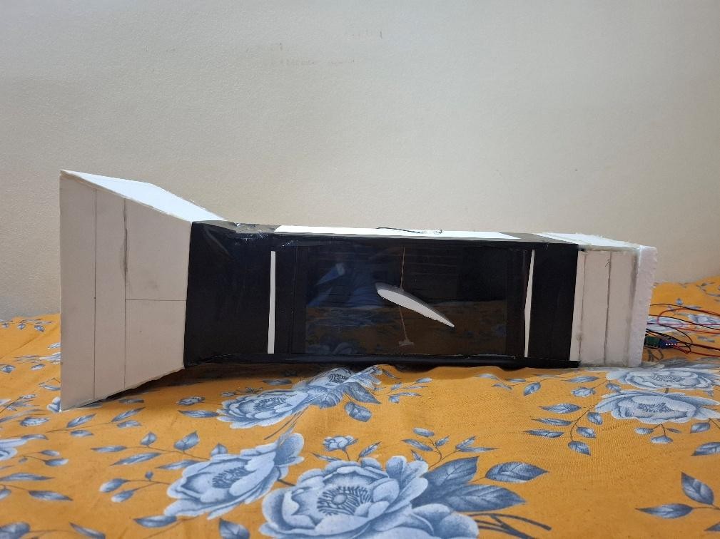
Figure 1: Fabricated wind tunnel setup with test section, aerofoil model, and smoke path
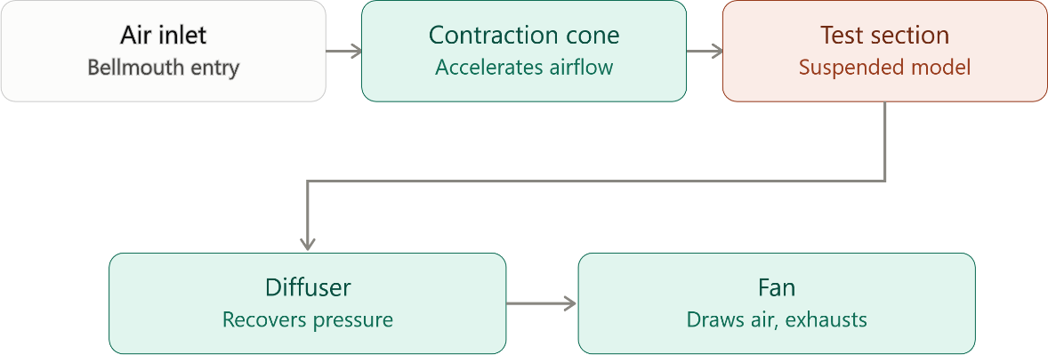
Figure 2: Flow diagram for the wind tunnel setup with test section, aerofoil model, and smoke path
To run the experiment, we generated smoke by hand using a homemade smoke generator and fed it into the tunnel’s inlet. Once the electric fan was switched on, it created a pressure difference along the duct that pulled air—along with the injected smoke—through the inlet, honeycomb, contraction, test section, and diffuser, in that order, just as outlined earlier. The aerofoil model was positioned in the center of the transparent test section, allowing us to observe the smoke streak lines flowing over its upper and lower surfaces and record them on video for later analysis.
Results
Once the fan had been switched on and smoke had been fed into the tunnel, a continuous, visible flow of streak lines was observed developing along its length. Near the inlet, the smoke was seen moving as a fairly wide, gentle stream; by the time it reached the contraction section, the same volume of smoke had visibly been thinned and accelerated, confirming what is predicted by continuity and Bernoulli’s principle: as cross-sectional area is reduced, velocity must be increased and, with it, the local pressure must be lowered.
In the test section, the smoke streak lines were observed following the curved upper surface of the aerofoil closely at low angles of attack, remaining attached and running roughly parallel to the surface — exactly the pattern that is attributed by theory to the faster-moving, lower-pressure flow above the aerofoil versus the slower, higher-pressure flow beneath it. This pressure imbalance was recognized as the mechanism behind the aerofoil’s lift, and it was found to align with the circulation-based explanation given by the Kutta-Joukowski theorem,
whereby lift per unit span is held to be proportional to the circulation generated around the body. When the model was tilted to a steeper angle, the smoke was seen being separated from the upper surface further back and broken into small, irregular swirls rather than a clean line — an early visual sign of stall behavior and reduced lift-to-drag performance.
Downstream, in the diffuser, the streak lines were observed spreading out again and being visibly slowed as the duct was widened, a pattern consistent with the intended pressure-recovery role of that section. Overall, the qualitative flow patterns that were observed were found to match the aerodynamic theory reasonably well, which was regarded as reassuring given that the entire apparatus had been built from foam board, cardboard, and a basic fan rather than precision laboratory equipment. The main limitations that were noticed included a slightly uneven smoke density (since the smoke had been generated manually rather than by a metered device) and some residual turbulence near the tunnel walls, which was thought likely to have arisen from small gaps or surface irregularities left over from hand-fabrication.
Conclusion
Classroom aerodynamics were turned into something that could actually be watched happening. A low-cost open-circuit wind tunnel was fabricated, complete with a bell-mouth inlet, honeycomb and screen flow-straighteners, a contraction section, a transparent test section, and a diffuser. Through this, a stable, visualizable airflow was generated using nothing more exotic than foam board, cardboard, and a household fan. Manually generated smoke was introduced into the flow, and through it, the movement of air around an aerofoil was directly observed: acceleration over the curved upper surface was seen, the pressure difference responsible for lift was developed, and eventually, once the angle of attack grew too large, separation into turbulent eddies was witnessed.
Beyond the aerodynamics itself, the project was treated as a genuine exercise in engineering trade-offs. Smoothness of flow was balanced against pressure losses, transparency against structural strength, and cost against performance, all while the work of a ten-member team was coordinated across design, fabrication, testing, and documentation. By the end, a working demonstration rig had been produced, a clearer intuitive grasp of lift generation had been gained, and a good sense of how much iteration goes into even a small-scale piece of aerodynamic hardware had been developed.