
Introduction
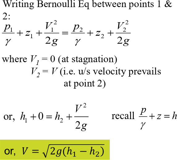
Measuring the velocity of a fluid without disturbing its flow has been one of the most enduring problems in engineering. One of the easiest ways to solve this problem is by using the Pitot-static tube, an invention that dates back to 1732 when it was used by Henri Pitot to measure the velocity of the Seine River. The instrument uses the principle of static pressure and stagnation pressure in order to determine the velocity of the flowing liquid using Bernoulli’s equation.
For this experiment, we decided to make an affordable version of this instrument using commonly available hardware store materials: two open-ended tubes as manometers, a submersible pump, and a plastic basin.
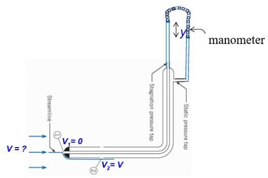
Figure 1.1: Basic principle of a Pitot Static Tube
Methodology
We kept the build simple on purpose, relying on materials that are easy to source and easy to replace if something breaks mid-experiment.
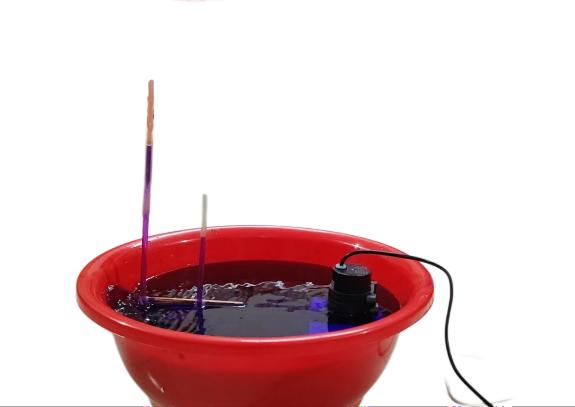
Figure 1.2: Experimental Setup
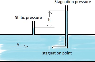
Figure 1.3: Demonstration of the basic principle of our project
Description of Setup and Components
- Basin: A large plastic basin filled with water, acting as the flow reservoir.
- Submersible pump: Placed at the bottom of the basin to drive a steady jet of water past the probe, giving a repeatable flow to measure.
- Stagnation tube: An L-shaped tube with its open end facing directly into the pump’s jet, so the water inside it is brought to rest and rises to the stagnation head.
- Static tube: A second tube mounted with its opening perpendicular to the flow, registering the static head only.
- Scale: A ruler fixed alongside the two tubes so the water levels in both, and their difference, could be read directly.
- Foam supports: Blocks of foam used under the pump and the tube assembly to keep both steady and at a fixed position in the basin during a reading.
Procedure
- The bucket is filled with water, and the pump is submerged.
- The Pitot-static assembly is positioned in the path of the flow generated by the pump. Allow the flow to settle for a few seconds so the water levels in both tubes stabilize.
- The difference in the water levels within the two vertical tubes is recorded.
- These height differences are then used to calculate the velocity of the water at that specific point.
Observations
|
Quantity |
Symbol |
Value |
|
Height difference between stagnation and static columns |
Del h |
10 cm = 0.1 m |
|
Manometer fluid |
—– |
Water |
|
Acceleration due to gravity |
g |
9.81 m/ s² |
Sample calculation
V = (2 × g × Dh) = (2 × 9.81 × 0.1) V = 1.962 m/s
Result
For a measured height difference of 13 mm between the stagnation and static tubes, the calculated flow velocity of the water at the probe location was: V = 0.505 m/s
This value seems reasonable for the flow conditions tested, and it confirms that the Pitot tube principle works well for measuring local velocity in a fluid stream. A few things could have introduced error here — reading the manometer by eye leaves room for parallax mistakes, and trapped air bubbles in the tubing can slightly skew the pressure reading. The flow may not have been perfectly steady either, causing minor fluctuations in the height difference. Even so, the result is close to what’s expected for this setup, so the experiment can be considered successful.
The Pitot tube experiment successfully demonstrated how pressure difference can be used to determine flow velocity. From the observed height difference of 13 mm, the calculated velocity was found to be 0.505 m/s, confirming that the device works effectively for velocity measurement in fluid flow.